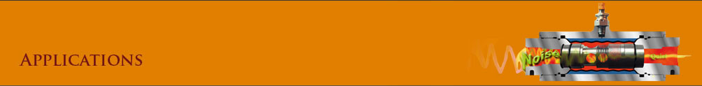
All quiet on the
hydraulic front
Hydraulic systems that run without making a lot of noise
don't just happen. They result from careful design and
well-planned installation strategies. Here are some ideas.
A. L. Hitchcox, managing editor
Many designers have long accepted leaks as inherent to hydraulic systems, even though advances in technology should have eliminated hydraulic leakage a long time ago. Hydraulics suffers a similar identity crisis when it comes to noise. Noise certainly cannot be eliminated, but a number of products and techniques exist to at least bring noise down to an acceptable level. The problem is that noise reduction is a complex subject, and spending a great deal of time, effort, and money may produce only modest improvements.
Sources of noise
A hydraulic system's greatest contributor to noise is the power unit. Noise not only emanates directly from the electric motor and pump, but also is caused by pressure fluctuations in the hydraulic fluid and by components - either resulting from these pressure fluctuations or from physical vibration. Allowing vibration of the pump-motor assembly to be transmitted to the reservoir can transform this physical vibration into sound - in the same way a loudspeaker transforms electrical vibrations into sound.
Electric-motor noise comes from bearings, the rotor and stator assembly (the characteristic hum), and, especially, the fan. A standard electric motor contains a fan with blades designed to provide cooling whether the motor shaft rotates clockwise or counter-clockwise. A fan designed for rotation in only one direction will generate less noise, so the expense of this option may be warranted if the application demands quiet operation.
Pump noise stems from rolling and sliding of bearings and pumping elements (vanes, pistons, rotors, gears, etc.), plus pressure fluctuations that result from the cyclical nature of the pumping process. Metal housings, whether part of the hydraulic pump or an electric motor, do little to prevent noise from being transmitted to the surrounding environment. Moreover, because the pump generally is coupled to an electric motor (and the coupling itself is a source of noise), noise control often involves treating the pump-motor combination as a unit (See box, "Small space... less noise", on page 48).
Valve noise has occurred in cabs of construction and other mobile equipment for years. Often, a high-frequency, random noise occurs when fluid, traveling at high velocity through the valve, undergoes a rapid and severe drop in pressure. This causes air dissolved in the fluid to form bubbles which, when they collapse, generate noise. Other types of noise - such as chattering, squealing, or buzzing - is generated when poppet-type valves do not seat properly.
Fortunately, most of these problems through better system design or by incorporating cushioning features into valves. A current trend replaces direct-operated valves with joystick-controlled electrohydraulic valves. This process of removing the hydraulics from the equipment cab offers a number of advantages beyond providing a quieter workplace environment.
Fluid conductors (tubing, hose, fittings), often are overlooked as noise sources. However, pressure pulsations in plumbing can distribute noise over a large area. Pressure pulsations can shake hose and tubing, causing rattling and eventual leakage.
Although reducing fluid-borne noise can be complicated, many manufacturers suggest rules of thumb to help reduce noise. For example, terminating a long run of metal tubing at each end with a section of hose helps isolate noise sources. One might be tempted to simplify the design by instead specifying a single section of hose. Hose, however, is very sensitive to pressure pulsations, so in long sections it can be a greater source of noise than metal tubing or pipe.
Securing tubing to framework with resilient clamps eliminates rattling and banging noise. However, care should be taken not to secure tubing too tightly, because lines may need to undergo thermal expansion. On the other hand allowing a tube to fit too loosely could cause wear as the tube constantly rubs against a metal surface or abrasive particles. Likewise. resilient grommets should be used when a hose or tube passes through a hole in framework, covers, etc.
Actuators, especially hydraulic motors, also generate noise. Hydraulic motors sometimes are considered to generate noise equivalent to that of pumps. However, hydraulic motors often operate at relatively slow speeds, so noise is not as much
Prevention and cure
The power unit generally holds potential for the greatest reduction in noise for a given amount of time, effort, and expense exerted. As mentioned. an optional cooling fan may reduce noise from the motor. Also, using a motor that operates at 1200 instead of the usual 1800 rpm may reduce noise. However, expect a 1200-rpm motor to be larger, heavier, and more expensive.
Pump noise may be reduced by running a large pump at a lower than normal speed (which can also increase pump life) or specifying four or five small pumps for a power unit instead of the usual one or two large pumps. Size and the type of pump (piston, vane, gear, etc.), number of pumping cycles per rotation, system pressure, and, especially, pump speed all influence noise. Again, check with the manufacturer for assistance in determining what parameters will best suit you application.
In addition to specifying quiet pumps and motors for the motor-pump assembly, you can also reduce noise by
• mounting tile pump and the motor to a subframe using vibration-damping mounts
• mounting the subframe to the power unit frame using vibration-damping mounts
• installing a flexible coupling between the motor and pump aligning it properly before startup
• using hose sections between tubing and components that are mounted to framework, and
• as a last resort, treating noise as a symptom rather than at its cause may be the only recourse for some applications. Installing sound-damping materials around the motor-pump or power unit not only adds expense and complexity to the system, but complicates maintenance and may hinder air circulation for cooling. Acoustic filters, which use internal reflections and resonant frequencies to cancel out noise, may also be effective. However, they must be tailored to the application and tend to be expensive.
Not allowing air to dissolve in hydraulic fluid goes a long way toward preventing cavitation both ill the Pump and in downstream components. Air can be removed most effectively when fluid is in the reservoir. Given enough time, air will separate from the fluid, so the path from the return line to the pump inlet should be as long and with as little turbulence as possible. In addition, incorporating a fine-mesh screen promotes removal of air. Furthermore, tests have shown that positioning a 60-mesh screen 300 from horizontal may remove as much as 90% of entrained air, Figure 2.
Another method of quieting the power unit is to reduce pressure pulsations. Accumulators often are specified for this purpose, but their effectiveness is limited because they dampen pressure pulsations within a range of frequencies for a given size and precharge pressure. Moreover, accumulator calculations are complicated, and several accumulators may be required to dampen the full range of pulsation frequencies experienced by a system.
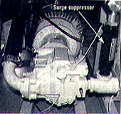
An alternative is to mount an in-line surge suppressor to dampen pulsations over a wide range of frequencies, Figure 3. Such a suppressor, manufactured by Wilkes & McLean Ltd., Elk Grove, Ill., consists of a housing containing an annular area that holds a pressurized charge of nitrogen, a cylindrical membrane, and a perforated tube, Figure 4. Under normal operation, fluid simply passes through the suppressor by entering one end of the tube and exiting the other. However, if pressure increases - from pump pulsation, for example - the fluid passes radially outward through the tube perforations, overcomes the nitrogen charge pressure, and expands the diaphragm outward. Allowing pressure fluctuations to act against the pressurized nitrogen cushions the vibration, so output pressure is much smoother - and, therefore, pump operation is quieter. Moreover, sizing is simple, because the suppressor is selected according to the size of the pump discharge line. |
Small space . . .
less noise
Cut-away view of Integrated Motor Pump (IMP). Hydraulic fluid enters the IMP inlet from the hydraulic system's reservoir, picks up heat as it passes through the motor, then is drawn into the pump and routed to the hydraulic system. The IMP shown uses a vane-type pump, but other models can accommodate piston and combination pumps.
The conventional pump-motor combination is the chief contributor of noise to hydraulic systems. Although pumps often are blamed for the majority of noise, the electric motors themselves are not blameless. Moreover, because heat generated by an electric motor must be dissipated to the atmosphere, large surface areas and cooling fins are employed to maximize the area from which the motor surrenders heat to the surrounding environment. This makes the air-cooled electric motor many times larger than the hydraulic pump it drives, even though they both have roughly tile same power rating.
Hydraulic pumps also generate noise from bearings' metal rolling elements. In addition, rolling and sliding of pumping elements (vanes, pistons, rotors, gears, etc.) plus pressure fluctuations that result from the cyclical nature of the pumping process produce noise. Metal housings, whether part of an electric motor of hydraulic pump, do little to prevent noise from being transmitted to the surrounding environment.
In an effort to reduce noise generated by hydraulic pumps, Vickers Inc., Maume Ohio, has introduced the Integrated Motor Pump (IMP). Originally developed for aerospace applications, the IMP does away with the conventional air-cooled motor to drive the hydraulic pump.
Instead, it relies on a custom-designed electric motor that is cooled by hydraulic fluid within the hydraulic system This electric-motor/pump combination is close coupled and housed within a sound suppressing enclosure.
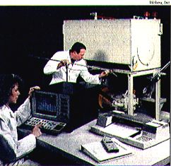
Recent tests conducted under measurement guidelines established by the Machine Tool Builders Assn., revealed, that a 20-hp IMP with a 5.9-in. /rev vane pump running it 1800-rpm operated at a sound level of 58 dBa Vickers compared this value roughly to that encountered in an average office environment and 16 dB lower (about 85% quieter) than, any available combination of conventional vane pump with air-cooled motor. A number of the IMPs will be installed power units by hydraulic systems used in the testing of engine components and transmissions at GM Powertrain, Romulus, Mich.
Cooling the hydraulic fluid not only reduces operating noise dramatically, but presents a side benefit of a much more compact pump-motor package. This is because:
• dynamic performance of the motor is improved from the closer tolerances that call be used, because large air gaps are not needed around the working members of the motor,
• components of the liquid-cooled motor can be made smaller, because they do not require a large surface area for transferring heat to the atmosphere, and
• the more-effective heat conduction of a liquid allows the motor to transmit more torque.
This last point is especially important because the mechanical power a motor can generate is limited primarily by temperature. Chuck Wall, marketing manager - Americas, at Vickers says that "There are four NEMA winding designs, and at loads less than 100%, there is very little difference between the NEMA designs. Each motor can operate at torque levels exceeding 100%, there is very little difference between the NEMA designs. Each motor can operate at torque levels exceeding 100% - but not continuously for conventional air-cooled motors. The differences [in torque ratings] are only significant in the range of 200% to 275% of full load torque."
Wall continues by explaining that applying a load exceeding 100% of rated full-load torque will overheat the motors' windings and eventually burn out the motor. "Motors are rated by their ability to stay cool using ambient air circulated by the motor's internal fan. Ratin is based on a motor's ability to provide acceptable wire insulation life at a particular temperature. Even a modest temperature increase over the insulation's rating significantly reduces life. But regardleoling medium]. Motors can produce much higher torque than indicated by their rating, without damage, if the heat, can be removed.
Oil [hydraulic fluid] is a much better conductor of heat than air is," explains Wall. "This higher conductivity provides much more effective cooling, and without the need for a cooling fan. Therefore, oil cooling allows the, Integrated Motor Pump's electric motor to generate torque that would overheat the insulation of an air-cooled motor and, ultimately, burn it out."
Wall says that oil cooling not only produces quieter operation, but also allows the motor to be physically smaller - 1.8 to 2.5 times smaller than an air-cooled motor, of equal power rating. And even with the sound-suppressing enclosure, the IMP is 35% to 45% smaller and weighs less than a conventional pump and air-cooled motor combination of the same power rating. The additional space increases access room for serviceability, allows mounting more components within the same space, or reduces the amount of floor space required by the hydraulic power unit.
Designers considering using the IMP must then decide whether to specify it because of its quiet operation or because it takes up less space.
|
Following is a copy of a
four page
article featured in
Hydraulics & Pneumatics Magazine.
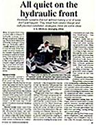
Fig. 1. Power units are notorious
for
generating most of the noise in a
hydraulic system. An important step
toward quieting them down
involves first
determining the nature and sources of noise.
Fig. 3. Surge suppressor, Shown installed on
pump outlet In Photo at right, takes up much
less space than accumulator. Oscilliscope
readings,
shown above, illustrate
how suppressor dramatically reducer
pressure pulsations, and, therefore, noise.
| Fig. 4. Surge suppressor uses pressurized nitrogen gas, elastic membrane, and metal tube containing hundreds of holes to dampen pressure pulsations. in cross-sectional drawing above, a sudden increase in pressure causes hydraulic fluid to flow radially outward, through holes in the perforated tabs, and against the membrane, which is loaded against a charge of nitrogen gas. At low fluid pressure, the membrane contracts around the perforated tube. The small size of the holes prevents the membrane from extruding through them. |
|