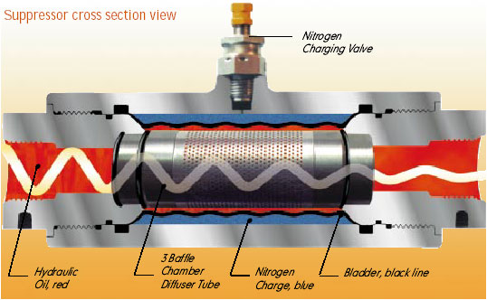
The hydraulic noise enters the Suppressor and goes through three different noise baffles or diffusers. In the picture above, these baffles are designated as #1, #2, and #3. These metal baffles are designed to convert 1/2" diameter holes to 1/32" diameter holes. The total radial distance through these baffles is only 1/4".
After passing through these holes the noise then strikes a nitrogen charged rubber tube, or bladder (#4). This bladder is usually charged with nitrogen to 70% to 80% of the hydraulic operating pressure. The 1/32" diameter holes are so small that the bladder cannot extrude them. The bladder deflects each time it is hit by a pulsation. This slight deflection of the bladder reduces the shock and noise. See animation of this procedure.
The sleeve like bladder, and it's ability to oscillate at a high frequency, plus the short distance each pulsation has to travel once it enters the Suppressor, explains the effectiveness of the Suppressor. |