| |
| |
 |
|
| |
| SUMMARY |
| Article discusses how to reduce hydraulic noise and possibly eliminate the use of enclosures to suppress noise in some applications |
| |
|
Hydraulic Noise Gets Suppressed
Noise has always been a problem in hydraulic systems. And both pump pressure and pump size have about equal effects on hydraulic noise levels. However, pump speed has about a 300% greater effect on pump noise than either pressure or pump size. Indeed, some pump manufacturers have been known to recommend slower electric motor speeds to solve the problem.
Noise problems are compounded by the use of hoses too. Laboratory tests show that pump noise levels are increased by 2 to 3 dB(A) just by adding 12 ft of outlet and return lines. The lines do not generate noise. Instead they radiate noise when they respond to pulsations or vibrations. The pulsations are usually generated by the pump and the vibrations are radiated by large flat machine surfaces.
Not only do hydraulic lines radiate noise, they quite frequently provide the primary path for propagating noise from the pump to components that, in their turn, react to the noise and radiate additional sound. This helps explain why a great many pump manufacturers have a very low dB(A) pump rating, but when the pump is installed on a power unit, the sound rating is much higher. |
|
It is almost impossible to forecast how much additional sound the hydraulic lines and surrounding structure will radiate. For this reason, many power units are enclosed after they have been manufactured and installed.
For many years, the problem of noise was solved by the use of nitrogen charged hydraulic accumulators. Initially, these devices were placed on the hydraulic line and it was hoped that the pulsations would enter the accumulator. However, in practice, pulsations bypassed the line leading to the accumulator.
Various different designs then evolved to try to solve this problem; in the main, the full flow was diverted into the accumulator. But the sizing of the design was difficult and the design was expensive. The pressure drop through the accumulators was also very high and created problem in some instances.
| The new Wilkes and McClean device, on the other hand, mounts an in-line nitrogen charged noise suppressor at the outlet of the pump. The tuning of the device is achieved by slight adjustments to the nitrogen precharge of the unit, an operation that is somewhat easier than wrapping the piping in sound absorbing tar or enclosing the entire power unit. |
Usually mounted directly at the pump outlet, the suppressor reduces the noise of a hydraulic power unit before it travels through the piping and radiates off other structural components. In operation, it performs the same function for a hydraulic line as a silencer does on a car: it makes the unit quieter by absorbing sound. The unit also reduces hydraulic pulsations and hydraulic shock - effects that can cause pump wear and cause leakage at tube or pipe connections.
When the device is actually installed in system, noise enters the suppressor and goes through three different noise baffles or diffusers. These metal baffles are designed to convert 1/2 inch diameter holes to 1/32 inch diameter holes. The total radial distance through these baffles is only 1/4 inch.
After passing through the holes, the noise then strikes a nitrogen charged rubber tube or bladder. This tube is usually charged with nitrogen at 70% to 80% of the hydraulic operating pressure. The 1/32 inch diameter holes are so small that the bladder cannot extrude into them. The bladder deflects each time it is hit by a pulsation, and this slight deflection of the bladder reduces both shock and noise. The large bladder area and the short travel distance combine to absorb high frequency pulsations over 600 Hz.
The suppressor has already found many applications. In one, a large pump manufacturer was requested to build sixty double pump power units for a large automotive company. They were required to meet a noise level of 80 dB(A). However, when they were completed, the noise level registered 82 dB(A). The pump manufacturer installed the new in line noise suppressor directly at the outlet of the pumps with the result that the noise level was brought down to 78 dB(A). |
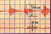
Figure 1. The Suppressor in operation.
Sensors, mounted immediately before
and after the suppressor provided the
tracings shown in the figure (below).
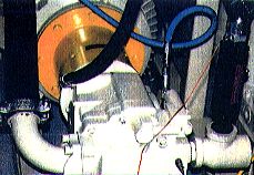
Figure 2. Main hydraulic pump room
with louvered doors.
|
| |
|
|
|
|
|
| |
|
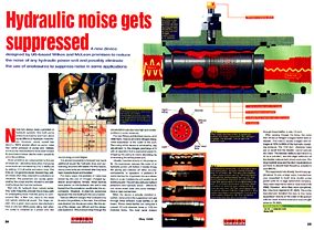
Figure 3. This cross section of the
Suppressor shows the outer
steel shell,
the nitrogen charge,
the bladder,
the oil and the diffuser tube. |
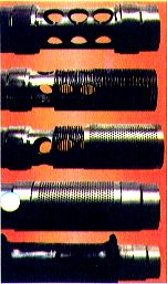
Figure 4. Construction assembly. (A) As fluid enters the suppressor, it flows radically through the 1/2 inch holes. (B) The second chamber is the compressed spring. Oil freely flows through the compressed spring. (C) The third radial flow chamber is assembled over the spring which is compressed over the 1/2 inch holes of the first chamber. Each chamber is sized to give adequate flow area for the fluid. (D) The assembled flow chamber shows that the original 1/2 inch flow holes have been converted to 1/32 in only 1/4 in radial distance. (E) The complete flow chamber fits into the bladder. |
|
| Figure 2. Noise enters the Suppressor and goes through different noise baffles. The noise then strikes nitrogen rubber bladder. |
| |
|
|
|
|
|
|
|
|