| |
| |
 |
|
| |
| SUMMARY |
| Suppressor mentioned in article as helping reduce noise in main auditorium. Also shows how and where suppressor is installed in system can make a difference. |
| |
|
Hydraulic Noise in Theme Parks
Hugh V. Jamieson III, Simulation Technologies, Inc., Durham, North Carolina
Howard K. Pelton, Pelton Marsh Kinsella, Dallas, Texas
Theme parks contain many mechanical systems not visible to the guests. Hydraulic systems are used to move show set pieces in response to the requirements of a ride and the audio systems. This article will describe typical hydraulic systems used in theme parks, how the hydraulic motive power is used to advantage and the problem of noise associated with these systems in relation to the noise criteria. The criteria can range from a low NC25 for auditoriums to a high of NC45 for interior ride buildings. The installation of the equipment, piping systems, vibration isolation and pulsation damping will determine if the criteria can be met. A case history will describe these points and how a problem was solved for an auditorium show space with a criteria of NC25.
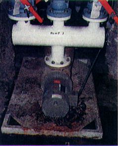
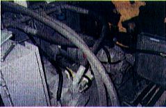
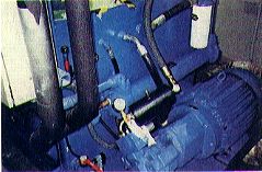
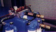
Theme parks are continuing to be built and expanded throughout the world. They provide family entertainment with shows, rides, dining and many exotic attractions. Some are based on famous movie themes. The view from the front of an attraction is what the operator wants the public to see as a means of attracting an audience. Behind the facade, as in most movie sets, there is another very different picture. A great deal of mechanical equipment is required to operate the attraction, ride or show. This takes the form of electrical motors, pneumatic systems with air compressors, hydraulic pump systems, large and small water pumps, sophisticated sound systems and a variety of air conditioning equipment. Examples are shown in Figures la and 1b. The purpose of this article is to describe a specific case history for an 800-seat attraction requiring low ambient noise (NC25) and the noise control solution for the main hydraulic pump system used to operate the various set pieces during the show. |
|
| The Building |
Figure 1a. Show effect water
pump located behind the set areas. |
| |
|
The construction of the main auditorium space was a part of an existing theme park with retail spaces integrated into existing buildings. A background survey revealed that noise from the park fireworks display every evening set the ambient level for the exterior building design. A tilt concrete building with heavy interior double gypsum board walls and a 6 in. concrete roof were selected to exclude the ambient noise as a means of achieving the interior criteria. Acoustical doors (STC55) were coupled with standard insulated doors and seals to isolate the attraction sound from the adjacent preshow area. Revealing too much of the show can spoil the effect.
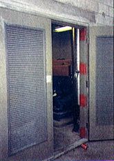
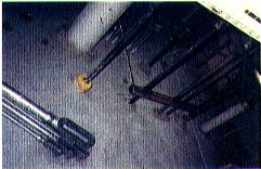
The air-conditioning system was designed for very low velocity with silencers downstream of factory built air handling units. The fans in the air handlers were vane axial and easy to silence. These units were located on the roof behind the stage. They had separate steel bases with high deflection springs. An exterior mechanical equipment room, with louvered doors for ventilation, housed the main hydraulic system (Figure 2). The hydraulic piping proceeded from this space throughout the main auditorium wall to various set pieces that were operated as part of the show (Figure 3).
The show was a 3-D, three screen production, based on a popular action-adventure film. There are a number of robots and other set pieces that operate at various times during the show, all powered by the main hydraulic power unit, HPU. In addition, a second hydraulic power unit was installed behind the stage and screen to operate a very fast system raising part of the screen during the show. The second HPU was equipped with a "quiet" pump that produced 67 dBA at 3 ft at full pressure and flow. This is shown in Figure 4 and the noise spectrum is shown on Figure 5. It did not affect the final results of the criteria in the auditorium.
The Hydraulic Noise Problem
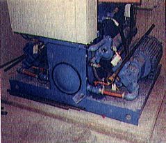
During the final stages of construction, it became evident that the main HPU operation posed a significant noise and vibration problem. Figure 6 illustrates the ambient levels in the auditorium from the main HPU, hydraulic fluid distribution system and SOLA rigging transformers and the levels in the hydraulic rooms. The HPU had minimal vibration isolation and piping was rigidly connected to the walls (Figure 3). The hydraulic pipes themselves produced a significant amount of vibration and typical hydraulic noise was very noticeable in the backstage area and auditorium. Figure 7 shows the hydraulic pump in the mechanical room prior to modification. The noise level in this space was 85 dBA upon start-up.
Noise in hydraulic systems is generated by two sources: mechanical vibration and fluid turbulence. Changes in a fluid's kinetic energy affect both mechanical vibration, the "water hammer" effect, and fluid noise, generation of turbulent flow. As sound travels in hydraulic fluid at approximately 5500 ft/ sec (the speed of sound in oil) and travels in the form of pressure waves, the "noise" analysis should focus on three areas: 1) the fluid's change in kinetic energy; 2) selection of line sizes to minimize turbulence; and 3) routing of the piping (in order to prevent changes in direction in close proximity to one another). In combination, one can achieve a "quiet" hydraulic system.
Analysis of the fluid velocity alone in the piping runs does not provide a complete picture. One must also look at instantaneous changes in flow and calculate the changes in kinetic energy.
Kinetic energy Ek is equal to the momentum p squared divided by twice the mass:
Momentum p is equal to mass m times velocity v. Since mass remains a constant, changes in kinetic energy are a function of the square of the fluid's velocity. In other words, if a line is insufficiently sized for flow changes through it, the changes in kinetic energy will be dramatic and a "water hammer" effect will be the result.
A pressure drop analysis of the piping system, as affected by line size, can significantly help complete the hydraulic noise picture. If the Reynolds Number Nr is <2000, the flow is laminar. If Nr is 2000-4000, the flow is transitional. Or, if Nr is >4000, the flow is turbulent (and audible). In general (including flow rate surges), if the pressure line fluid velocity is held under 15 ft/sec and return line velocity is held under 10 ft/sec, the Reynolds number will remain below 4000 and turbulent flow will exist only at changes in direction (for example at elbows and tees).
The final area of analysis is the pipe routing itself. As the fluid is forced through a change in direction, such as an elbow fitting, Bernoulli forces cause the fluid to become turbulent and remain so for approximately ten internal line diameters of distance before returning to laminar or transitional flow (again line size dependent). As a rule-of-thumb, if at all possible, a change in direction should not occur within a distance equal to ten internal line diameters.
For this particular theme park system, the noise problem arose from three identifiable sources:
• Noise generated at approximately 262.5 Hz and traced to the 9 pistons of the hydraulic pump being
driven at 1750 RPM (15,750 pressure pulses/min or 262.5 pressure pulses/sec).
• Mechanical vibration from somewhat rigid piping connections.
• Turbulent flow in certain sections of the building's piping which was already aggravated by the
mechanical coupling and solid connection through walls (see Figure 3).
Discussion of Solutions
The solutions were threefold:
• Damp the pump fundamental pulsation.
• Reduce turbulent fluid flow by reconfiguring the discharge piping system.
• Isolate the system from the building structure.
Damped Pulsation. The solution to the 262.5 Hz pulsation noise was to install a noise suppression damper into a "tuned" chamber/column. Wilkes and McLean manufactures an in-line noise suppression damper which in reality is an in-line small volume hydraulic accumulator. The damper was fitted with a sharp 900 elbow fitting on its outlet and a sweep elbow on its inlet which in turn was closely coupled to the pump outlet. This combination formed a "tunable column" shown in Figure 8. The combination of the sweep elbow, the body of the damper, and the sharp (exit) elbow formed a "chamber" which closely approximated the length of 10 internal line diameters and had pulse absorption capabilities. The precharge on the damper was set at approximately 50% of the system pressure. Figure 9 shows the main HPU prior to final modification. Although a damper was installed, it was insufficiently sized and improperly located to be effective. The installation and location of the damper combined with discharge piping can result in less than desirable results.
Isolation of the System. Mechanical vibration from the motor and pump was being transmitted into the piping and structure as the "piping system's" connection point was rigidly attached to the HPU reservoir and lid. The HPU reservoir and lid acted as a drum head, thus, amplifying the noise and transmitting mechanical vibration. The fluid connection point was, in actuality, a heavy steel manifold housing the system filters.
Remounting this heavy manifold onto vibration isolation mounts, allowing the manifold to act as an inertia block, isolated the mechanical vibrations of the HPU from the piping. The mass of the flexible hoses versus the mass of the manifold was in excess of 10:1. The manifold was connected to the building piping via flexible hoses with sweep elbow fittings.
Reduce Turbulence. Inside the building, one particular piping section, suspended from the ceiling by long anchor rods, had three changes in direction in close proximity to one another (right 90°, left 90°, down 90°). The section was "free" to shake everything it could "touch" as well as being a perfect "speaker" and radiator of fluid noise.
The solution here was twofold:
• Refit the primary flexible connection to the building piping (hoses) with sweep 90° elbow fittings
(versus 90° elbow fittings) as mentioned above.
• Replace the multiple turn section of piping with a hose which took on an 'S' like shape where the
bottom one-half of the 'S' was rotated 90°. The bend radius of the hose resulted in a change of
direction over an excess of 30° inside line diameters.
Consequently, no turbulent flow was generated and laminar flow was achieved throughout. The final result in the hydraulic room is shown in Figure 5. There was about a 10 dBA reduction by adding a properly sized and located pulsation damper and modifying the piping system to isolate and reduce turbulence. The final ambient noise level in the auditorium is shown in Figure 10. The slight peak at 500 Hz is from the new "quiet" hydraulic system added behind the stag
| SUMMARY |
| The audience reacted to this high quality show with standing ovations. The quiet auditorium and mechanical system plays a significant role in delivering this product. As the demand for increasingly exotic entertainment intensifies, more thoughtful design of mechanical systems to meet lower noise criteria will be required. While noisy roller coasters have been the norm, the need for extremely quiet auditoriums for specific shows and rides inside buildings, where the audio content of the program is critical, will play a larger part in the whole spectrum of theme park acoustical design and noise control. This whole field will continue to be a major factor in the design and expansion of theme parks. |
|
Figure 1b. Typical hydraulic pumps for
show action figures.
Figure 2. Main hydraulic pump room
with louvered doors.
Figure 3. Hydraulic piping through
wall in mechanical room.
Figure 4. New quiet hydraulic
pump behind stage area.
Figure 5. Levels in hydraulic room
under three conditions: 1)
initial
operations; 2)
first modification; 3)
final installation of damper.
Figure 6. Noise levels in the auditorium
from HPU, piping and SOLA rigging
transformers and mechanical room.
Figure 7. Initial installation of
hydraulic pump system. |
Figure 10. Final ambient levels
in
auditorium. |
Figure 8. Proper installation of pulsation
damper on hydraulic pump discharge. |
Figure 9. Initial installation of
pulsation damper.
|
| |
|
|
|
|
|
|
|
|
|
|