| SUMMARY: |
| This SAE paper describes the noise generated by curved hoses and compares the noise reduction of accumulators vs. the Suppressor.
(SAE stands for: The Engineering Society For Advancing Mobility Land Sear Air and Space International) |
Copyright 1995 Society of Automotive Engineers, Inc.
400 Commonwealth Drive, Warrendale, PA 15096-0001
Reprinted from: Fluid Power, Applications, Standards, Noise, Lubricants, and testing (SP-1110)
ABSTRACT
In the past if there was a noise specification to be met, the hydraulic circuit designer selected a pump, from a manufacturer's catalog, that showed a low decibel rating. However as the power unit was manufactured the noise level usually turned out to be higher than that shown in the pump catalog. The problem is that any slight noise generated by the pump is amplified throughout the hydraulic circuit. This paper deals with a new method of stopping the noise before it can be amplified.
INTRODUCTION
A person need only walk through a large automotive company and he will pass some hydraulic power units that have sound enclosures built around them. The sound enclosure is often an indication that the power unit did not operate at the sound rating shown in the catalog for the pump. In other words the catalog pump sound rating is usually much lower than the sound rating for the completed hydraulic power unit.
Something happens during manufacturing a hydraulic power unit that changes a relatively quiet pump into an unacceptable noisy power unit. Pump pressure and pump size have about equal effect on hydraulic noise. However the pump speed has about 300% greater affect on pump noise than either pressure or pump size. This is the reason some pump manufacturers recommend slower electric motor speeds. Fixed displacement pumps are usually quieter than variable displacement pumps. But all of these variables are shown in the pump catalog. In addition to these variables something else is contributing to an increase in noise that is not mentioned in the pump catalogs.
Lab tests show that pump noise levels are increased by 2 to 3 dB(A) just by adding 12 feet of outlet and return lines. The lines do not generate noise, instead they radiate noise when they respond to pulsations or vibrations started by the pump. The pulsations are usually generated by the pump and these vibrations are transported by the hydraulic lines to large flat metal surfaces were they are converted to the higher noise level.
So not only do hydraulic lines radiate noise but they frequently provide the primary path for propagating noise from the pump to components that, in turn, react to the noise and radiate additional sound. This helps explain why many pump manufacturers have a very low dB(A) pump rating, but when the pump is installed on the power unit the sound rating is much higher.
It is almost impossible to forecast how much additional sound the hydraulic lines and surrounding structures will radiate. This is why many power units are enclosed after they have been manufactured and installed at the customer's plant. The sound enclosure is a result of the additional noise generated by the close proximity of additional large flat machine surfaces.
To get to the source of the majority of noise in any hydraulic system one has to start with the pump. The pump is the main source of the pulsations. The pulsations are the cause of the noise and vibrations. The Piston pump manufacturers seem to have recognized the inherent problem in the piston pump design and are making an effort to correct the noise problem. However after the hydraulic pump designer has done his best, every pump 'still produces a pump ripple. "Ripple" is the pump manufacturers name for pulsations. It is this ripple or pulsation that produces line vibrations which cause additional noise. Until recently most pump manufacturers ignored the transmission of these pulsations because the methods of trying to eliminate them were too expensive and the transmission and radiation of the pulsations was considered to be the circuit designer's responsibility. This paper deals with new inexpensive methods of reducing the transmission of these pulsations and thus reducing the entire circuit noise level.
It is this ripple or pulsation that produces line vibrations which cause additional noise. Until recently most pump manufacturers ignored the transmission of these pulsations because the methods of trying to eliminate them were too expensive and the transmission and radiation of the pulsations was considered to be the circuit designer's responsibility. This paper deals with new inexpensive methods of reducing the transmission of these pulsations and thus reducing the entire circuit noise level.One of the first things that should be reviewed when attempting to reduce power unitFigure 1 noise is the hydraulic lines. The one source that contributes the most to adding noise is the incorrect use of hydraulic hose. Recent research at a large pump manufacturer showed that they were able to take an average of 5 dB(A) out of a standard power unit merely by changing the configuration of the hydraulic hose (see fig. 1). In the past, a 90 degree curved hose was used when a horizontal line had to be connected to a vertical line. A 180 degree curved hose was also quite common.
Research has shown that both of these configurations actually increase the noise level in the system. The solution is to not bend hydraulic hose but to use a metal tubing for any bend and only use hose in a straight line (see fig. 2). |
|
|
It is common knowledge that introducing a compressible median of nitrogen into the relatively incompressible medium of hydraulic fluid will help reduce pulsations. However the problem here is how do you get the fluid to merely bounce off the nitrogen so the nitrogen compresses and the fluid merely loses its pulsation and nothing more. |
| Through the years the nitrogen charged hydraulicFigure 3 accumulator has been used in most circuits to absorb hydraulic pulsations. At first the accumulator was used as an appendage device. It hung on the hydraulic line and the designer hoped that the pulsations would enter the accumulator (see Fig. 3). However practice showed that the majority of the pulsations bypassed the line leading to the accumulator. Then various different designs evolved in which the full flow was diverted into the accumulator (see Fig. 4). Sizing this type of accumulator is complicated and the design that diverts the flow into the accumulator is very expensive. The pressure drop through these accumulators is also very high and can create a problem. |
|
|
A new method of dealing with the noise causing pulsations is to mount an in-line nitrogen charged noise suppressor right at the outlet of the pump. This new design is a departure from the usual accumulator design. To understand this new design concept, merely think of a hydraulic line with 4158 small radial holes in it and a nitrogen charged bladder pressing down on the holes (see Fig. 5). The holes are large enough to permit fluid flow but too small for the bladder to extrude into them. This new devise is exceptionally small. The length of the unit for a 3/4' size 3000 P.S.I. pipe line is only 8.25". The cost of the unit is usually about one fifth of the price of the larger surge suppressor type accumulators. Another big advantage is that there is no engineering involved in selecting the unit. The size of the unit is determined by the size of the existing hydraulic line. There is an in line suppressor for every pipe and tube size from .375' to 3". In the past the sizing for a hydraulic pulsation dampener was a long and complicated process. With the new design the size of the line becomes the size of the suppressor. |
border="0" cellspacing="0" cellpadding="0">
 |
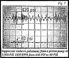
However more important than ease of sizing is how well the unit suppresses the pump pulsations and why it works better than other types of accumulators. It is more effective than a much larger accumulator because the fluid only flows .25" radially before it comes in contact with the bladder. Often when using an accumulator the flow path is at least four or five inches long before the fluid contacts the bladder. This short flow path coupled with the fact that there is a much greater flow area leading to the bladder makes the suppressor much more efficient. To date the largest piston pump manufacturers have used the suppressor to help them meet or exceed the strictest automotive noise standards. Figures 6, 7, and 8 show the results of the suppressor tested at pressures from 750 PSI. to 4000 PSI. and at both 1200 RPM and 1800 RPM.
 |
 |
|
One large pump manufacturer made sixty double pump power units for a large automotive company. When they were completed the noise level registered 82 dB(A). The automotive noise specification that had to be met was 80 dB(A). The pump manufacturer decided that the least expensive solution was to install the new in-line noise suppressor directly at the outlet of the pumps. This simple solution brought the noise level down to 78 dB(A). The cost was considerably lower than building a noise enclosure around the entire power unit.
CONCLUSION
The first thing to consider when trying to reduce noise in a power unit is the configuration of the hoses used in the lines leading from the pump. Whenever possible try to eliminate any curved sections. Replace all curved sections with bent tubing. If additional noise reduction is required consider using an in-line noise and shock suppressor. This in-line noise suppressor actually does not reduce the noise level of the pump. That is like trying to unring a bell. However, it can reduce the pump pulsations that enter the hydraulic system and by reducing the pulsations, it reduces the vibrations, and thus the noise radiated by the vibrations. So now the power unit designer can look up the noise level of a pump in the manufacturer's catalog and with the use of the suppressor, he can expect that will be the total noise level of the hydraulic power unit after it is assembled. |
|